|
|
|
|
|
|
Additional Resources: Warning Before Beginning New Construction | New Construction Resources | Sample Specifications.
Our services include: Commerical, Residential, Utility & Agriculture and Snow-melting.
|
|
| Commercial:
Warehouse
Offices
Schools
Nursing Homes
Outdoor Warming Areas
Car Wash Areas |
Residential:
New Construction
Additions
Garages
Whole House or Selected Areas
Retrofits and Heating Upgrades
Pool Decks |
| Utility-Agriculture:
Green House and Soil Heating
Repair Shops
Agricultural Utility Sheds
Hangers
Livestock and Kennel Facilities |
Snow-melting:
Store Entrances
Resorts
Nursing Homes
Driveways
Runways
Anywhere Snow and Ice Need to be Removed |

 Radiant floor heating is experiencing a huge resurgence. It is simple and versatile while providing quiet, clean, healthy, comfortable, and efficient heat. You can have simple radiant systems with a boiler or water heater and also use the hot water for radiators, baseboards, towel warmers, convectors, fan coils, and domestic hot water generation.
Radiant Panel Heating has been successfully installed in concrete slabs on grade, concrete slabs on wooden sub-floors, concrete post tension slabs, under the floor joists, in the plaster in ceilings, and in the walls. The following general guidelines provides an overview of the important steps in the proper design and layout of slab and under-floor radiant heating systems. A well designed system will not only simplify installation, but will also assure maximum energy savings and comfort levels. Our knowledgeable design staff and local representatives are available to assist in any aspect of your system design and installation.
Site Preparation: Slab on Grade
The soil must be compacted and level with special care taken to assure the proper drainage. A high moisture content of the soil can rapidly extract heat from a radiant slab affecting the system's output, efficiency, and response time. As such, a plastic vapor barrier should be installed below the radiant heated slab. In addition, crushed stone placed on top of the compacted soil is an excellent drainage medium and is recommended for any below grade (basement) areas or those susceptible to water accumulation.
Insulation below a Radiant Heated Slab: Rigid Polystyrene or Polyurethane with a recommended 2" and a minimum of 1".
For colder weather climates, the proper insulation under a radiant slab will greatly increase the efficiency and responsiveness of the system. The "how and where" of adding the insulation is based on the required system designed and the gained cost/benefit relationship. In milder climates, the use of insulation under the slab is generally not required nor recommended.
As a radiant slab heats up, it also heats the soil beneath it. In most applications, this will result in only a small decrease of efficiency and responsiveness. For applications installed over bedrock, clay, other high heat sink materials or where ground water is a concern, a layer of crushed stone as well as insulation may be critical for the proper operation of the system.
Perimeter Insulation
The perimeter of a radiant slab accounts for the majority of the slab heat loss. In fact, an un-insulated radiant slab operating at 80° F. with an outside temperature of 10° F., can lose as much as 150 BTU/Hr for each lineal foot of slab perimeter. It is recommended with the relatively low cost and tremendous benefit of perimeter insulation that it be installed for all radiant slab applications.
Site Preparation: Suspended Slab
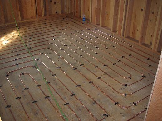
Suspended slabs will most commonly occur over wooden sub-floors in the upper level wood frame construction. The sub-floor should be structurally sound and swept clean. Roofing felt paper, 15-30 lb, should be applied over the entire floor area and secured in place before installing the radiant panel circuits.
Insulation under the Slab Installed on a Suspended Wooden Sub-floor: Type, Fiberglass Batt with a recommended 6 times the R-Value of the floor covering with a minimum of 3 times the R-Value.
Suspended floor construction over an unheated basement or crawl space should always be insulated in order to minimize the heating requirements of the room above and maximize the efficiency of the radiant system. When installing the radiant panel over a heated area, it is still recommended to insulate between the floors to prevent downward heat transmission.
Piping Sizes and Layouts
The piping sizes in most radiant panel circuits regardless of the materials used generally ranges from 3/8" - 1". The radiant floor piping layouts are based on three operational considerations that must be effectively balanced:
- the requirement to maintain a relatively even slab temperature;
- to provide enough heat as defined by State requirements for a specific heated space;
- to provide increased output needed along exterior surfaces where the heat loss is greatest.
 The actual piping layout will be determined by the design of the experienced Hydronic Engineer. Under no circumstances should it be determined by the Contractor without design experience. A set of plans must be provided identifying all patterns and layouts for the tubing and each circuit should be installed with no more than 2" deviation from these specifications. This allows for quick identification of the tubing location after the pouring of the concrete.
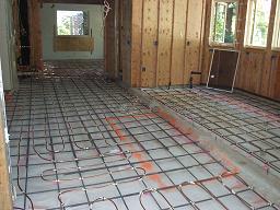
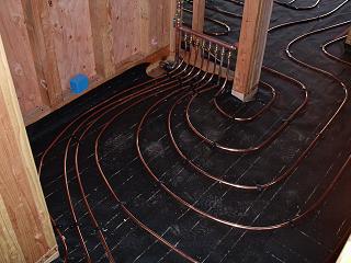
Layouts may be either single, double, or triple serpentine patterns with lengths not to exceed 200 feet. Serpentine patterns allow for the hottest water to border the exterior or perimeter which is the point of highest heat loss. We never recommend counter-flow patterns for radiant panel installations since this results in uneven slab temperatures, making it unacceptable in exposed floor circumstances. The normal spacing patterns for the tubing is 6-18" depending on the slab thickness and the heating requirement. In areas of extreme heat loss, more tubing can be installed. During the past 40 years, ANDERSON RADIANT HEATING developed specific formulas which defined the tubing size, spacing requirements, and tubing lengths necessary to heat an area by providing the proper BTU output at a given flow rate.
Installing the Pipe and Slab Thickness
The minimum recommended slab (thermal mass) thickness for the radiant panel is:
- 1-1/4" for 3/8" pipe
- 1-1/2" for 1/2" pipe
- 1-5/8" for 3/4" pipe
- 2" for 1" pipe
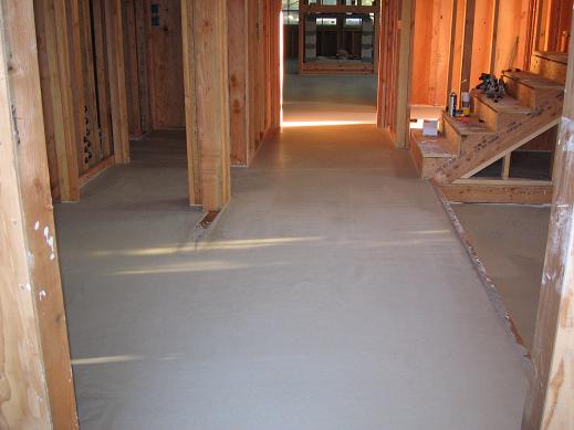
The typical slab thickness when installed on a raised foundation construction (wooden sub-floor) is 1-5/8" to 2" which is provided by framing the wall plate with an extra 2" x 4" plate depth. The concrete is then poured to the first plate level. As most slabs on grade will be considerably thicker, 4"- 6", these minimums are primarily only a concern for suspended floor applications. When the pipe is secured to the wooden sub-floor, these minimums provide a tubing coverage of 7/8"- 1".
For thicker slabs the optimum tubing depth is centered in the slab, usually 2"-3", in order to provide effective thermal dispersion and response. Deeper placement of the tube in thicker concrete slabs will in most instances still provide a highly successful system. However, an increase in the supply water temperature and a decrease in response time can be expected. The use of both perimeter and under slab insulation is recommended only when deeper pipe placement is utilized or the system is installed in cold climates. Structurally permitting, a slab may also be split into two individual pours with an inch or two of rigid insulation placed between. In split slab applications, and ideally all slabs, fiberglass strands should be added to the concrete to provide added strength.
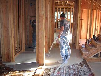
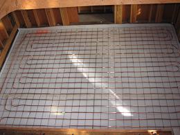
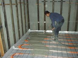
Prior to pouring the concrete, the pipe depth in a slab on grade applications is maintained by the securing of the pipe to a "cold" steel wire mesh or rebar grid. The mesh may then be supported at the desired height with adobe blocks or lifted in place at the time of the pour by the Masonry or Hydronic Contractor. Pour supervision should always be the responsibility of the Hydronic Contractor to ensure no tubing is damaged when the concrete is applied. Care should be taken to assure a uniform pipe depth is maintained, as variations in depth can result in uneven surface temperatures.
Securing the Pipe
For slab on grade applications, the tubing should be secured to wire reinforcing mesh or rebar with plastic ties. Secure the tubing every 36"- 48" to prevent pattern displacement when the concrete is poured. Small sticky foam insulation, commonly referred to as handicap wrap, can be cut into small pieces and placed between the rebar and piping. This serves to cushion the pipe from denting when the concrete personnel step on it during the concrete pour. Contact of the two dissimilar metals (the copper tube and steel rebar) will not effect the piping. There will be no electrolysis or degradation of the tubing because of the system's "CLOSED-LOOP" environment.
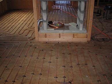
Pipe installation on a suspended slab over a wooden sub-floor should be with plastic plumbers tape and steel wood screws. Place the plastic straps every 36"- 48" with additional placement at bends or where the pipe visibly rises.
If the radiant floor installation requires a second slab to be installed over an existing one (a two-slab pour), 15-30 lb. roofing felt can be laid between the two slabs with a 6" cold steel wire mesh for fastening the tubing circuits. The purpose of the wire is to hold the proper circuit patterns while assisting in the structural integrity of the slab.
Expansion Joints and Slab Penetration
Slab settings or shifting over time can possibly cause damage to the tubing as it crosses the area of stress. Thermal expansion and contraction of the piping is not of concern because of the moderate operating temperatures of the system. The tubing should always be protected whenever it enters or leaves a slab and as it passes through any expansion joint. Piping may also be dipped under an expansion joint and buried in the subsoil in place of passing directly through the joint. In all circumstances, a sleeve of polyethylene insulation or fiberglass wrap placed around the pipe for a minimum of 6" on each side of the penetration will help protect the piping.
Bending the Tubing
Care must be taken during the installation to bend the copper tubing into the identified patterns. Bend supports are not necessary for the actual pipe layout within the floor areas. However, if the tubing does get kinked during the installation, it must be cut out and repaired.
Manifold Connections
After completion of the radiant tubing installation and prior to pouring of the concrete, the temporary manifold connections may be made. It is generally not practical to install permanent system manifolds and flow control valving at this time. A temporary manifold will allow pressure testing of the system before and after the pouring of the concrete and during continued construction. The pressure test will insure the tubing is leak-free and remains leak-free during the construction phase. If another Contractor were to drill or hammer through a pipe during their work, it will easily be identified and the necessary repairs can be performed. The sealed manifold will also prevent unwanted debris from entering the tubing system.
The permanent manifold connections are either soldered or silver-brazed and constructed of wrought-copper fittings. To prevent the possibility of any leakage, no compression fittings are allowed when connecting the tubing circuits to the manifold headers and flow control valves. Located on the manifolds are balancing or flow control valves for every circuit. This allows individual balancing of the heat for each room. Often, an automatic zone control valve will be located on the manifold header as well. In copper tube radiant panel systems, only an above ground return manifold is necessary, unlike plastic systems where both supply and return manifolding is required. This makes the copper system more aesthetically pleasing with less cluttered wall space and closets.
System Testing and Start Up
All concealed radiant panel heating systems are hydrostatically tested to 150 PSI for 24 hours before the slabs are to be poured and remain on indefinitely during construction. By doing this, if anyone damages a portion of the tubing it can be identified and repaired. Connecting the circuit patterns to a common manifold enables the entire system to be easily pressurized at once. If the system fails to maintain pressure or a pipe is punctured by another trade during the pour or construction, the leak must be located and repaired. This is one reason why pour supervision must be performed by the Hydronic Contractor. All leaks repaired in or under the concrete slab caused by on-site damage, will be silver-brazed with a minimum of 15% silver content and the system retested.
System Purging
All radiant panel systems which are properly designed will contain purge valves on the boiler. Each zone should be individually purged on completion of the system installation and prior to boiler start-up. This is accomplished by closing the main boiler supply and return valves and using a fast-fill water supply to purge the air from each circuit. The balance valves on the common manifold can be individually operated to purge the circuits or the main zone control valve can be manually used to accomplish the same. After all the air has been visibly removed and the water runs quietly through each circuit you can proceed to the next zone or circuit needing purging. Repeat this process until all the zones are filled with solid water.
System Balancing
Balancing valves for each room circuit are located on the common manifolds. The valves allow for individual adjustment of loop water flow where circuit lengths differ more than 10%. Proper balancing is obtained when the return water temperature of each loop is maintained at the closest level. The exceptional radiant panel design will require no balancing and the normal position of the system flow control valves is fully open.
Temperature Adjustment
Temperature gauges mounted on the boiler supply and return mains and at the manifold locations allow for accurate monitoring and adjusting. Since the circuits in the properly designed system are of relative equal lengths, the resulting flow rates required for proper and even heating require very little adjustment. However, the manifolds allow the homeowners added control to meet their needs for different room temperatures. With temperature gauges installed, boiler or mixing valve output can be confirmed, verified, and adjusted to meet the design requirements.
System Operations
With the completion of system purging, balancing and temperature adjustment, along with the complete mechanical checkout of the boiler and its safety and support equipment, the thermostatic or outdoor reset controls of the system can be initiated and normal operation established.
ANDERSON RADIANT HEATING
520 East McGlincy Lane, Suite 16
Campbell, CA 95008
Phone: (408) 378-3868
Fax: (408) 559-0818
© Copyright 2012 - ANDERSON RADIANT HEATING
Privacy Policy
|
|
|
|